No products in the cart.
Projects
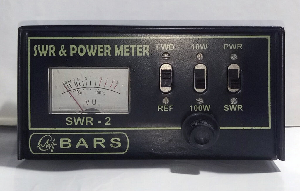
SWR Meter
26
Feb
Feb
What is an SWR Meter?
An SWR meter, or Standing Wave Ratio meter, is an electronic device used to measure the standing wave ratio of a radio frequency (RF) transmission line. It is commonly used in the field of radio communication to ensure that a transmitter is operating efficiently and safely.
Why use SWR Meter?
When Source and Load Impedance match, that is they are equal, optimum power transfer can occur.
In case of AC, mismatch causes a part of the Forward (outward) power supplied by the Source to be reflected back from
the Load, causing Standing Waves which are sum of the Forward and Reflected waves.
End result – low transmission efficiency and in the worst case a fried transmitter.
The Circuit
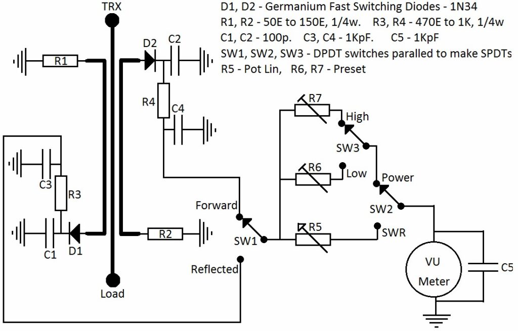
Simplified Description
There are 2 PCBs – one for mounting the switches and presets, the other PCB is a directional coupler.
On the directional coupler PCB, the center track carries the power from the Source to the Load. Forward and Reflected
powers are sensed by the 2 tracks on either side. Rectification and measuring is then done to calculate the Standing Wave
Ratio.
SWR = {1+(Reflected/Forward)} / {1+(Reflected/Forward)}
Also, if (Z_source) which normally is 50 ohms and (Z_load) are the source and load impedances respectively, and we have a
purely resistive dummy load, the equation very roughly approximates to :-
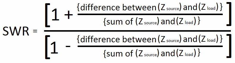
So for a source (transmitter) impedance of 50 ohms, dummy loads (Z_load) of 50 ohms, 75 ohms, 100 ohms and 150 ohms
should give SWRs of 1 : 1, 1.5 : 1, 2 : 1 and 3 : 1 respectively.
You can also calculate other dummy load values for finer calibration of the meter scale.
Preparation of PCBs
The SWITCHES PCB – cut the 2 tracks as shown in the picture and put a jumper.
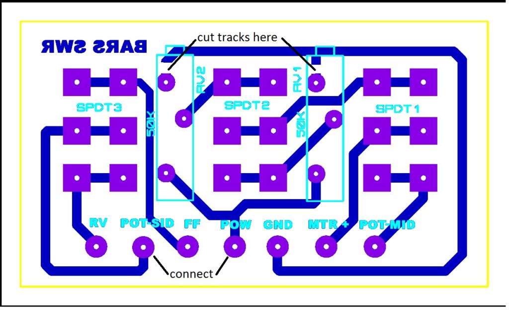
The MAIN PCB – drill & assemble as per instructions below
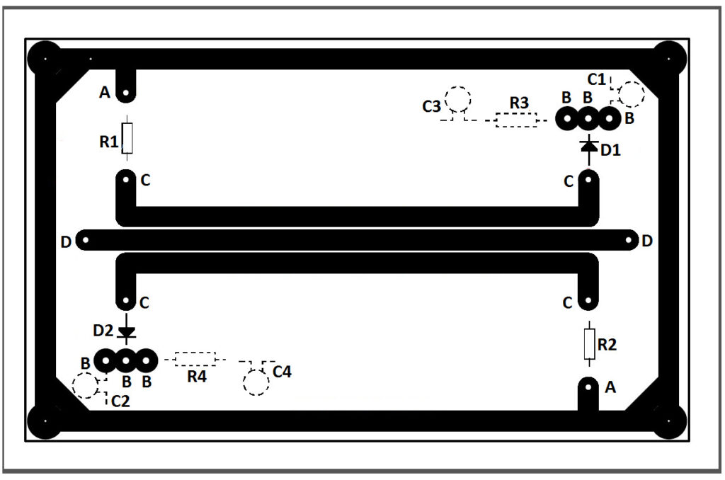
A – drill 0.8mm holes, component leads will be soldered on both track and backplane sides
B – drill 0.8mm holes, then use 3.0mm drill bit to remove back plane around the hole. soldering only on the track side, no
contact with the back plane
C – no hole here, component leads soldered SMD style
D – drill hole to suit center conductor of coaxial cable, then use 3.0mm drill bit to remove back plane around the hole.
coaxial cables’ center conductor connect here from the back plane side and out to SO239s. coaxial cables’ braids are
soldered to the back plane. when soldering, try to keep the coaxial cables in a straight line with respect to the center track
R1, R2, D1, D2 – mounted on the track side
C1, C2, C3, C4, R3, R4 – (shown in broken lines) mounted on backplane side. cut 2 pieces (about 3 or 4 mm square) of scrap
copper clad PCB and glue them on to the back plane to make islands for the C3/R3 and C4/R4 junctions
Testing and Calibration
Initially, start up with R1 & R2 as 50 ohms.
Connect up as per circuit.
The sensing PCB should face track side down and parallel to cabinet base.
Connect 50 ohm dummy load to instrument output.
Set potentiometer to 1/4th way up.
Set switches to SWR & Forward positions (High Power / Low Power switch position does not matter).
Set transmitter to lowest power.
Connect transmitter to instrument.
Transmit and adjust potentiometer to give full scale deflection.
Switch to Reverse / Reflected position.
Transmit – the meter should show very little no deflection.
If meter shows substantial deflection in the Reverse / Reflected position, experiment by changing R1 & R2 till deflection in
the Reverse / Reflected position is almost zero – use equal values of R1 & R2 every time. This is done to make the
instrument compatible for 50 ohms source and load.
Next, set switches to SWR & Forward positions.
Transmit and adjust potentiometer to give full scale deflection.
Note this reading.
Do not change the potentiometer setting.
Interchange the transmitter and dummy load connections to the instrument.
Switch to Reverse / Reflected position.
Transmit – the meter should show exactly the same deflection as in the previous operation.
This verifies that the instrument is symmetrical. If not – check whether everything is correctly done.
After all the above results are satisfactory, connect transmitter and dummy loads to the correct sockets.
Try out the instrument again with the 50 ohm dummy load – in Forward position, adjust to full scale deflection and check
for zero deflection in Reflected position.
Now to graduate the scale for different SWRs.
Take off the meter’s plastic cover and stick a piece of paper on the meter’s scale.
Obviously, the zero deflection position is the SWR = 1 : 1 position.
Now put in the 75 ohm dummy load (for which a SWR of 1.5 ; 1 is expected).
Set switches to SWR & Forward.
Still using the lowest transmitter power, transmit and adjust potentiometer to full scale deflection.
Switch to Reflected and mark the reading – that is your 1.5 : 1 SWR point.
Repeat the above operations with different dummy loads and mark the different SWR points.
Note – the 3.0 : 1 SWR mark is expected to come at the center of the scale.
DO NOT TRY TO TRANSMIT WITHOUT ANY DUMMY LOAD TO SEE WHAT INFINITE SWR LOOK LIKE .
While you are at it, it would be a good idea to home brew a small collection of QRP dummy loads for various SWRs for
further experimentations.
Now that your SWR meter is ready, you might want to calibrate it to use it as a power meter also.
Always use 50 ohm dummy load of adequate rating / capacity for this operation.
Switch to Forward and Power position.
Select High or Low Power as required.
Transmit known amount of power and adjust the respective preset to give the deflection that you want and mark
accordingly on the meter’s scale.
And you are done – happy experimenting.
Yes, it does sound too like much work, but that is what ham radio and home brewing is all about – developing and
sharpening your skills.
73s from BARS.